Tamalpais Valley Railroad

We move stuff there and back again


Home

Community

Contact

Humor

Links

Wireless DCC

Arduino

Articles

Micro Book

X2011 Convention

LED Lighting

Donner Summit Progress

Feb 18 Frog Power

Jan 18 DIY DCC Decoders

Jan 8 - Donner Summit v3

Jan 6 09 - Slim Princess

Oct 23 - Sound Xperiment

Oct 15-Construction Start

Sep15 - Main St Colfax

Sep 1 08 - Focus Stacking

Aug 15 08 - Colfax Depot

Aug 4 08 New Layout 2

Jul 31 08 New Layout Plan

Jul 22 08 - Snow in Ogden

Jul 19 08 McCloud Railway

Jul 8 Solar and Profits

Jun 27 08 AC-12 4294

Jun 23 08 Donner Trip

Jun 19 08 SP GP9 #5623

Jun 18 08 Depth of Field

Jun 16 2008 Craftsman Kit

Jun 15 2008 Cab Forwards

Jun 14 2008 Rivet Count

Jun 13 2008 Why?

Jun 12 2008 White Balance

Jun 11 2008 Photography

Blog

Gallery

Gallery 2

Videos

Construction

How-to

Water

Trees

Grass

Terrain

Servo Switch Decoder

Trackplan

Prototype

SP Railroad Atlas


Arduino for Model Railroading
I have been building a few Model Railroad related Arduino projects lately.

microCS - A DCC Command Station
The unit is based on the Arduino R3 Motor Shield. You will need a genuine one if you want the ability to read-back decoders while programming and over-current sensing.
The microCS is a basic command station.  It makes a nice unit for your workbench or a small layout.  If you've ever wanted to be able to modify your command station, here's your chance.  Make the default loco your favorite number or hard-program in some turnout routes. Why not if its yours.

Hardware for the microCS

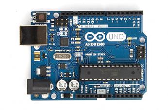
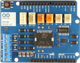
You can use just about any Arduino Uno compatible board.  I used a real Arduino Uno R3 and I tested a knockoff, the Sain, which also worked nicely.  However, you will probably want the genuine Arduino Motor Shield.  It has a current sensing feature that actually works and is sensitive enough to capture the read-back pulse of a DCC decoder.  I started with a Pololu motor shield but it was not sensitive enough, while the cheap China knockoffs don't seem to have any current sensing at all.  The other use of current sensing, besides decoder read-back, is for over-current protection in case of a short.
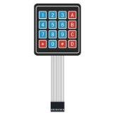
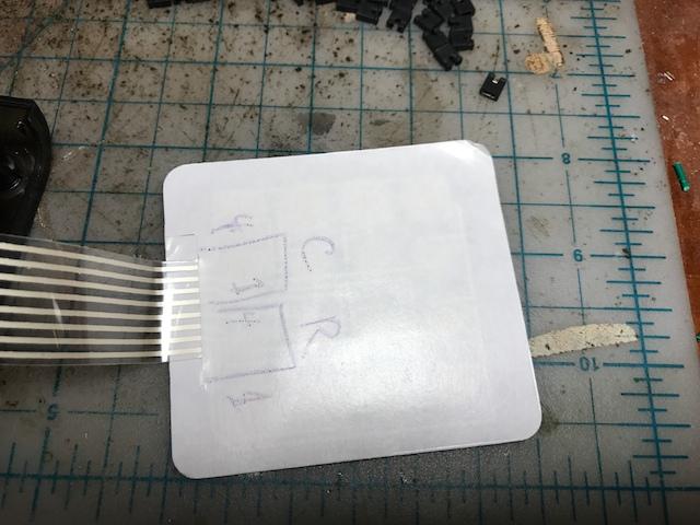
For the keyboard I used a 4x4 matrix type that is easily available.  You can use another brand without any trouble. Or you could use a matrix of 16 pushbuttons.  It takes 8 pins (4 for the columns and 4 for the rows), and that pretty much maxed out the Uno, but it performs really nicely.  The key action works ncely and there is pressure feedback that lets you know when you have pressed the button.
The throttle is a linear 5K potentiometer with a center detent.  The clockwise side of the detent is forward and the other direction is backward with zero at the center. Fairly hard to find such a pot but I found one at Digi-key.  I did program the pot with a fair amount of deadband around zero so you can probably get away without the center detent.  Some folks may not like having the reverse be built in to the speed control like this.  By changing the code you could add a reverse button and have the pot control the full range.
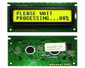
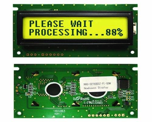
For the display I used a Newhaven serial display in I2C mode.  (NHD-0216K3Z-FL-GBW-V3) Originally I used it on a 9600 baud serial softport but this turns off interrupts while sending and played havoc with the DCC signal which depends on interrupts for accurate timing.  In the end I used a simple I2C software hack to send commands with bit-banging.  As there is no need to ever get anything back from the display, the code is send only.  You can use other displays but you will need to know what you are doing as the code will need some rework. In the end I didn't do a great job (at least from the point of view of the software gods/software zealots) in seperating the display code as it made things too big and I ran out of programming energy.  I will have to live with the shame.
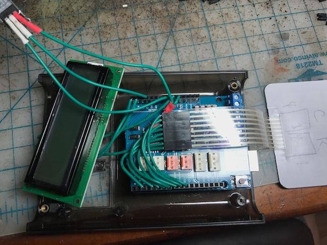
I put the whole thing in to a Adafruit Arduino case.   It is a bit big but it has a nice feel in the hand. The motor shield being a bipolar type is not very efficient and produces a fair amount of waste heat and so I left the bottom plate of case entirely off for more circulation.
READ THE COMMENTS IN microCS.cpp TO SET UP THE HARDWARE.

A Newhaven NHD-0216K3Z-FL-GBW-V3-ND serial display in I2C mode was used. If you use other brands of I2C display you will need to change the command codes as they are Newhaven specific.
I used a 4x4 matrix keyboard. It took 8 pins but it works nicely and is simple.
Document
This file contains the code. Put it in your Arduino directory. Be sure to read the comments in microCS.cpp on how to set up the hardware!
microCS Software
Here is a zip of the project.  If you are familiar with Arduino programming you will have no problem.  If you are not then you should embark on a crash course using some Arduino examples and try altering them.  It took me a few days to figure the Arduino IDE and programming out.  The Arduino is remarkably well done and documented.  My code contains a lot of comments to help you out that I won't repeat here.
I used hardware interrupts to get the DCC timing to work and keep the DCC running in the background while the code processes other things.  This will make the code opaque to the beginning Arduino/microprocessor user and required reading the Atmel data sheets.  It also makes it less the code less portable (but not impossibly so as I ported most of this from a PIC32 that I started my DCC coding on).  It might be possible to write a DCC command station that just uses standard Arduino commands.  Show me that I am wrong.
The DCC commands are in their own file and are portable to other platforms. However, this is not a comprehensive library.  It contrains 95% of what a DCC command station needs but more advanced features are left out.   Life is just too short and I also didn't include anything I couldn't easily test on real hardware.
One nifty feature I put in is the ability to understand a subset of the SPROG commands from JMRI.  If you tell JMRI that an SPROG command station is on the USB port, then you can send throttle commands through the USB connection to the microCS and control a locomotive from the computer.  Once that is running you can run the JMRI WiFi server and control trains from your smartphone.  Instant wireless throttles.  This is definitely the greatest thing JMRI group has done since the toaster.

You will also need to install the Arduino Keypad library.


Construction

The internal wiring is shown here.  Use #22 solid wire - this fits neatly in to the Arduino headers. The motor shield need to be modified to make it fit in the Adafruit case.  Shorten all of the long pins on the bottom by an 1/8 of an inch.  This will allow it to sit down lower.  Also cut off the red and white plastic tabs on the top and all the pins associated with these.  These will not be used and they prevent the case from fully closing.  Finally the 2 brake connections need to be cut on the bottom of the board as we will need these pins.
The potetiometer needs 3 wires, +5V and ground to the outsides and the middle wiper to A2. IF the pot direction is reversed, swap the ground and 5.5V wires.
The +5V will be shared with the display so you need to splice 2 wires together.
There are 2 grounds so one can be used for the display and the other for the pot.

A look at the back of the keypad with how the rows and columns are laid out.  Refer to the Micro_CS comments to match the rows and columns to the proper pins.

#define ROW1 2
#define ROW2 4
#define ROW3 5
#define ROW4 6
#define COL1 7
#define COL2 8
#define COL3 9
#define COL4 10


The NHD-0216K3Z-FL-GBW-V3 LCD display needs to have a jumper on R1 (pads on the back that you solder a small wire between - you can see it in the lower image at left on the right side) added to put it in to I2C mode.  
The connections are to the P2 connector which has 6 pins (holes). Pin1 is square. Ignore the 3 pin connector.
SCL pin 3 - connect to A5 on Arduino
SDA pin4 - connect to A4
Gnd pin 5 - connect to Gnd
VDD pin 6 - connect to 5.5V


© Copyright 2012 by Duncan McRee, All Rights Rreserved - dmcree at tamvalleyrr dot com

Website powered by Network Solutions®